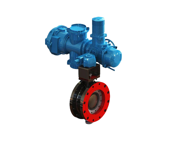
Common Failures of Special Motors for Control Valves
The specialized motors used in control valve actuators play a crucial role in industrial automation. Their performance directly affects the opening, closing, and flow control of control valves. Therefore, it is essential to ensure the proper functioning of these motors and prevent common failures. This article will analyze the common causes of motor failures, propose preventive measures, and provide a comprehensive discussion on motor selection, installation, and maintenance to ensure the long-term stable operation of the control valve.
The specialized motors for control valves typically have a fully enclosed squirrel-cage structure. They operate on a short-time intermittent duty cycle, where the motor works for 10 minutes and then automatically cools down. These motors are widely used in control valve actuators to provide the necessary opening and closing torque, as well as precise control. The motors are often equipped with temperature control switches to prevent overheating due to prolonged use or overload.
The protection level of the motor may vary depending on the control valve's working environment and operating conditions. If the protection level is insufficient, moisture, dust, or foreign objects may enter the motor. This can damage the motor's insulation, leading to equipment failure. Therefore, it is important to implement effective protective measures during both use and storage.
To protect the motor from external environmental factors, the packaging of control valve actuators must provide protection against rain, moisture, and dust. The packaging should be firm and reliable. During transportation, special care must be taken to prevent the motor from being exposed to rain, which can reduce its performance. Once the actuator reaches the site, it should be stored in a well-ventilated, dry environment. It is important to avoid outdoor storage to prevent moisture buildup.
It is particularly important to avoid commissioning or maintenance work during rainy weather. After commissioning, all fasteners must be tightened to ensure that the electrical seals are reliable. This will help prevent moisture from entering the motor and avoid other faults.
Motor selection is crucial, especially when matching the opening and closing torque with the motor load. The opening and closing torque should be calculated based on the control valve's actual operating torque and its inherent torque value. If the torque is too high, the motor may be overloaded. If the torque is too low, the control valve may leak. Therefore, when selecting the motor, make sure that the rated opening and closing torque is at least 1.1 to 1.3 times the control valve's actual operating torque. This will ensure that the motor has enough capacity to handle unexpected situations.
Control valve actuators typically include a micro switch, which is an essential component in the control mechanism. If the control valve's travel exceeds the preset position, the micro switch will promptly disconnect the power supply. This provides overload protection. Most actuator manufacturers combine travel protection with torque protection. If over-travel or over-torque occurs, the micro switch will immediately cut off the power, protecting the motor from damage.
There are two main installation methods for control valve actuators: horizontal and vertical. In vertical installations, where the motor's tail end is positioned downward, the motor may be susceptible to the failure of cable sealing components. If the seal fails, lubricating grease may enter the motor through the cable outlet, causing short circuits and damaging the motor. To avoid such failures, ensure that the cables and seals are intact during installation and conduct regular inspections.
Additionally, the direction of rotation for the actuator handwheel should be consistent with the output shaft rotation direction. Typically, turning the handwheel clockwise closes the control valve, while turning it counterclockwise opens the control valve. If the motor's rotation direction does not match the required direction, correct it by switching any two phases of the three-phase power supply. Incorrect rotation direction may cause the motor's protective measures to fail, leading to motor damage.
The specialized motors for control valves are designed for high-load, short-time duty cycles. These motors are suitable for control valves that frequently start and stop. However, if the operating time is too long or the load is too heavy, the motor's temperature may rise. This can reduce the motor's insulation rating and potentially damage the motor. Therefore, it is essential to control the motor's operating time and load to avoid overload operation.
Control valve actuators come in two types: torque-type and thrust-type. Torque-type actuators typically use three-jaw or key connections and do not bear axial thrust. Thrust-type actuators, on the other hand, most often use threaded connections and can handle larger axial thrust. During installation, ensure there is sufficient clearance between the control valve mating surface and the actuator. This will prevent interference and ensure the proper meshing of the worm and worm gear to achieve the rated output torque.
The control valve motor is equipped with a temperature control switch. This switch automatically disconnects the power supply when the motor is overloaded or operates for too long. If the motor temperature exceeds the set limit, the temperature control switch will disconnect the control circuit, protecting the motor from damage.
To ensure the long-term normal operation of the motor, establish a regular inspection routine. For actuators that have not been used for long periods, periodically test the insulation resistance of the stator windings. This will help prevent motor failure due to insulation aging or other factors.
In conclusion, the common failures of control valve motors are closely related to motor selection, installation, maintenance, and the operating environment. To ensure the motor's long-term stable operation, consider selecting a motor with sufficient margin to prevent overload. During installation, ensure good sealing to protect the motor from environmental factors. During commissioning and operation, strictly control operating time and load to avoid overheating. By implementing preventive measures and performing regular maintenance checks, the service life of the control valve motor can be effectively extended. This will ensure the reliability and stability of the control valve system and support the smooth operation of industrial automation systems.

