Design and Installation for Three-Way Control Valves
On this page
Three-way control valves are pivotal components in fluid control systems, renowned for their distinctive design features and extensive application spectrum. They play a crucial role in both industrial production and energy management. The design characteristics of these valves not only determine their operational performance but also impact the efficiency and stability of the entire system. Understanding the design features and installation steps of three-way control valves is essential for ensuring the proper functioning and high efficiency of the system.
Three-way control valves are key equipment widely used in fluid control systems, with design features that make them significant in various industrial applications. Here are the main design features of three-way control valves.
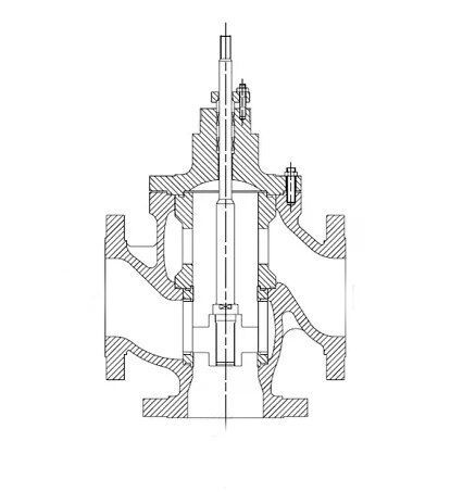
Three-way control valves are equipped with two valve plugs and seats, similar to double-seat valves. However, in a three-way control valve, when the flow area between one valve plug and seat increases, the flow area between the other valve plug and seat decreases. This is in contrast to double-seat valves, where the flow areas change simultaneously.
The air-to-open and air-to-close functions of three-way control valves can only be achieved by selecting the direct and reverse actions of the actuator, unlike double-seat valves, which can change air-to-open and air-to-close by directly reversing the valve body or plug.
Suitable for control systems requiring fluid ratio, three-way control valves can replace both an air-to-open control valve and an air-to-close control valve, thereby reducing costs and saving installation space.
In applications before heat exchangers, a diverging three-way control valve is used; after heat exchangers, a converging three-way control valve is applied. Due to different fluid temperatures, leakage may be significant, and it is generally recommended that the temperature difference between the two fluids does not exceed 150°C.
The use of a valve cage guide and a balanced hole design significantly reduces unbalanced forces and aids in stable valve operation. Early three-way control valves reduced unbalanced forces by guiding the valve plug side, but significant unbalanced forces could still occur when the fluid was close to closing. The balanced hole valve cage structure effectively eliminates unbalanced forces and provides damping, contributing to the stable operation of the control valve.
Proper installation of three-way control valves is key to ensuring their normal operation and the stability of the system. The following are detailed installation steps for three-way control valves.
Read the manual: Before installing, carefully read the product manual. The manual provides installation requirements, operating instructions, and maintenance suggestions for the equipment, which can help avoid errors and omissions during installation.
De-energization operation: Ensure that the relevant power supply is cut off before installation to ensure safety. Installation should be performed by technically qualified personnel to avoid equipment damage or safety hazards due to improper operation.
Flow direction: The flow direction of the valve must be consistent with the arrow on the valve body. This is a basic requirement to ensure the valve's functionality.
Valve body location: The valve body should be installed above the drain pan to ensure that any dripping water falls into the pan, avoiding the impact of dripping water on the surrounding environment.
Vertical installation: The valve body and actuator should be installed within a ±60° range of the vertical direction. At least 30mm of space should be left above for disassembly and maintenance.
Maintenance space: Sufficient maintenance space should be maintained between surrounding pipelines, equipment, and buildings to ensure that maintenance personnel can easily access the equipment through maintenance holes for inspection and maintenance.
Actuator installation order: Only after the valve body is installed and the pressure test is passed can the actuator be installed. This is a key step to ensure the system's safety and normal operation.
Avoid exerting force: During the installation and commissioning process, if the actuator is already installed on the valve body, external forces should be avoided to prevent damage or performance degradation of the actuator.
Electrical commissioning: After installation, conduct power-on commissioning. At least three complete operating cycles of the actuator should be observed to ensure that all parts are operating normally. After the no-water commissioning is qualified, then conduct the water test. The pressure difference of the system's up and down water must be strictly controlled within 0.15MPa to ensure the effectiveness of the three-way control valve.
Mastering the design features of three-way control valves and the correct installation steps is the foundation for ensuring the stable operation of the system. By thoroughly understanding the valve structure, air-to-open and air-to-close functions, fluid ratio control, bypass control applications, and the advantages of the valve cage structure, one can better optimize system performance. At the same time, strictly following the installation steps can effectively avoid common problems, enhance the reliability and service life of the equipment. Whether in design or actual application, precise installation and comprehensive understanding will help the three-way control valve to perform optimally in various application scenarios.

