Installation Requirements and Considerations for Control Valves
On this page
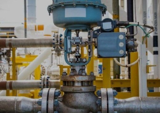
Control valves are critical components in industrial control systems, primarily used for precise regulation of fluid flow, pressure, or temperature to ensure process stability and efficiency. Proper installation is essential for maximizing the valve's performance and ensuring long-term reliability. This guide provides a comprehensive overview of control valve installation requirements and considerations to help ensure optimal performance and safe operation.
Process Requirements: Install control valves according to the design requirements of the process flow. Position the valve near related primary instruments to facilitate clear observation during manual operation with a bypass valve.
Operation and Maintenance: Place control valves on the ground or a platform for easy access, ensuring convenient operation and maintenance. The valve should be easily reachable for routine inspections and maintenance tasks.
Vertical Installation: Typically, control valves should be installed vertically on horizontal pipelines. In special cases where horizontal or inclined installation is necessary, additional supports must be provided to ensure the valve's stability and functionality.
Vertical Installation: When installing a valve group (including control valve, bypass valve, shut-off valve, and drain valve) on a vertical surface, position the control valve below the bypass valve. This arrangement prevents the bypass valve’s drainage from affecting the control valve’s operation. For valves with a nominal diameter smaller than 25mm, they can be installed above the bypass valve to accommodate spatial constraints.
Clearance Requirements: The clearance between the bottom of the control valve and the ground or platform should be at least 400 mm to ensure adequate maintenance space. For valves with a reversed valve core, allow sufficient space below the valve body for core extraction. Ensure a minimum clearance of 2 mm above the top of the control valve diaphragm head to avoid interference.
Shut-off and Bypass Valves: Use gate valves for shut-off applications and globe valves for bypass valves. For bypass valves with a nominal diameter greater than 150 mm, gate valves can also be used to ensure precise flow control. Avoid aligning shut-off valves and control valves in a straight line to prevent fluid interference and operational difficulties.
Drain Valve: Install a drain valve at the lowest point of the pipeline between the control valve’s inlet side and the upstream shut-off valve. Use a gate valve for draining to prevent liquid accumulation that could impact valve performance.
Solid Particle Media: For pipelines with solid particles, arrange the control valve and bypass valve on the same plane or place the bypass valve below the control valve to avoid particle impact on the valve.
Support Requirements: For pipelines operating at high or low temperatures, use one fixed support and one sliding support for the control valve group to accommodate pipeline displacement and thermal expansion.
Environmental Requirements: Install control valves in environments with temperatures ranging from -40°C to 60°C and away from vibration sources to prevent environmental impacts on the valve.
Area Arrangement: When multiple control valve groups are present in one area, ensure uniform valve types for neatness, aesthetics, and ease of operation.
Reducer Installation: When the diameter of the control valve differs from the shut-off valve, install reducers close to the control valve to minimize flow resistance and uneven flow.
Cleaning and Inspection: Ensure both upstream and downstream of the control valve are clean and free from blockages. Conduct pressure tests on the pipeline system before use, with test pressures typically exceeding normal operating pressures to confirm the valve and its components can withstand the test pressures.
Filter Installation: Install filters upstream of the control valve to prevent debris or impurities from damaging the valve. For equipment requiring continuous operation, install a bypass valve during control valve maintenance to maintain system functionality.
Flow Direction and Capacity: Ensure correct installation direction to guarantee proper flow direction. The valve body casting usually indicates the flow direction with an arrow. Ensure the valve has appropriate flow capacity to keep pressure drops within acceptable limits.
Separator and Drain Valve: Install a steam-water separator and a drain valve to prevent condensate from flowing through the control valve, which could shorten the valve’s lifespan. Drain points are crucial for closed valves to prevent severe consequences from water hammer effects. Separators and filters ensure good steam quality.
In summary, proper installation of control valves enhances system efficiency and significantly extends equipment life. By adhering to these detailed installation requirements and considerations, you can ensure the stability and reliability of control valves under various conditions. Whether it involves selecting the location, arranging valves, installing supports, adapting to environmental conditions, or ensuring proper filtration and protection, meticulous installation work is key to ensuring smooth operation and process stability.

