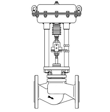
Maintaining Pneumatic Actuators for Optimal Control Valve Performance
Pneumatic actuators play a crucial role in automated systems, translating control signals into mechanical movements to mainly drive control valves. However, even the most reliable equipment can experience malfunctions, making timely troubleshooting and maintenance essential. Below is a detailed analysis of common issues with pneumatic actuators and their respective solutions, including scenarios involving control valves.
1. Power Supply Issues
Issue: Power indicator light is off, feedback from the control board is absent, and the actuator remains inactive.
Possible Causes: Faulty power indicator light or inadequate power supply.
Diagnosis and Solution:
Check the fuse to ensure it's intact and examine the status of the power indicator light.
Use a multimeter to test for continuity in the indicator light circuit. If necessary, replace the defective indicator light.
If power supply inadequacy is suspected, inspect the power supply module and associated wiring to ensure proper voltage levels.
2. Signal Control Problems
Issue: Open signals are effective, but close signals fail to actuate.
Possible Causes: Malfunctioning feedback circuit or damaged control components.
Diagnosis and Solution:
Verify the integrity of the feedback circuit for any breaks or short circuits.
If issues persist, inspect components such as the close indicator light or controllable thyristor for defects and replace them accordingly.
3. Directional Control Malfunctions
Issue: Actuator movements are unresponsive to input signals.
Possible Causes: Faulty current-limiting resistors, phase-shifting capacitors, or motor winding issues.
Diagnosis and Solution:
Use a multimeter to check the resistance of the motor winding. If irregularities are detected, consider replacing the motor.
Verify the functionality of current-limiting resistors and phase-shifting capacitors and replace them if necessary.
4. Power Supply Failures
Issue: Tripped circuit breakers or burnt-out fuses in the control board.
Possible Causes: Short circuits in the motor winding or malfunctioning brake mechanisms.
Diagnosis and Solution:
Test the motor winding resistance with a multimeter. A near-zero resistance indicates a short circuit.
Check the resistance across the terminals of the brake mechanism. An infinite resistance suggests a malfunction, requiring component replacement.
5. Motor Anomalies
Issue: The motor remains inactive despite signal inputs.
Possible Causes: Rotor issues or obstructions in the motor winding.
Diagnosis and Solution:
Directly apply power to the motor winding to determine if it operates properly.
Clean any accumulated dust or debris around the rotor and motor end caps to ensure unhindered movement.
6. Control Board Failures
Issue: Actuator movements are not controlled by the control board.
Possible Causes: Malfunctions in motor windings, current-limiting resistors, or phase-shifting capacitors.
Diagnosis and Solution:
Conduct thorough inspections of motor windings, current-limiting resistors, and phase-shifting capacitors for functionality.
Address identified issues through repair or replacement as necessary.
Effective troubleshooting and maintenance of pneumatic actuators, including those integrated with control valves, require technicians with a solid understanding of electrical principles and ample practical experience. By employing systematic fault identification and resolution, optimal system performance can be ensured. Rigorous testing and calibration following maintenance procedures are essential to restore equipment, including control valves, to its peak operating condition.

