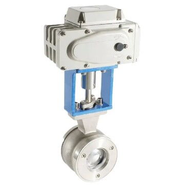
Power Systems & Installation for Electric V-Port Ball Valves
On this page
Electric V-port ball valves are efficient devices widely used for fluid control in various industrial applications. Their distinctive design enhances performance, making them popular in many sectors. However, the configuration of the power supply and electrical control systems is critical for their optimal operation. This article discusses essential factors related to the power supply, electrical control system design, and installation directions for electric V-port ball valves, ensuring reliability and efficiency in real-world applications.
Electric V-port ball valves generally operate on either AC (alternating current) or DC (direct current) power. When designing the power supply system, several crucial aspects must be considered.
AC Power: Commonly used in industrial settings, AC power is suitable for most standard valve operations. It can support high-power devices and is relatively straightforward to install and maintain.
DC Power: Typically employed in applications with specific needs, such as automation control systems or low-voltage environments. DC power delivers stable current, facilitating high-precision control.
Choose an appropriate power voltage based on the rated voltage of the V-port ball valve to ensure compatibility. Maintaining stable and reliable voltage levels is vital to prevent fluctuations that could negatively impact valve performance and lifespan. For voltage-sensitive applications, voltage regulation devices may be necessary.
Calculate and configure the power capacity based on the V-port ball valve's power requirements and operating conditions. Consider peak loads and additional equipment demands to ensure the power supply meets the valve's operational needs under various conditions. It is also advisable to reserve some spare capacity for unexpected situations.
For critical applications, consider implementing a redundant power supply system. By configuring dual power sources or backup supplies, you can ensure that the valve continues to operate normally in case of a primary power failure, thereby enhancing system reliability.
The electrical control system for electric V-port ball valves comprises controllers, electric actuators, sensors, and other related devices. Key design considerations are as follows.
Choose an appropriate control method based on actual needs, which can include manual control, automatic control, or remote control. Devices like buttons, switches, or programmable logic controllers (PLCs) can enhance operational flexibility. For highly automated systems, intelligent control systems can optimize adjustments based on data.
Determine the type of control signals needed, such as analog, digital, or pulse signals, and select suitable transmission media (e.g., cables, fiber optics). Ensure signal stability and reliability to prevent control failures due to signal interference. Signal isolators and filters may be employed to enhance the system's resistance to interference when necessary.
Select appropriate sensors based on the specific requirements, such as position sensors, pressure sensors, or temperature sensors, to monitor and feedback the valve's status and operating conditions in real time. Utilizing a combination of sensors can provide comprehensive monitoring capabilities, improving system intelligence.
Incorporate safety features such as overload protection, short circuit protection, and overvoltage protection to ensure the V-port ball valve can safely shut down or switch to a backup system during abnormal situations. Consider implementing emergency shutdown systems and fault alarm systems to facilitate timely responses to issues, minimizing potential risks.
Proper wiring and connections are crucial when designing the electrical control system for electric V-port ball valves. This ensures reliable signal transmission and minimizes electrical interference. Here are some recommendations.
Choose cables with anti-interference capabilities and ensure reliable connections. Different signal types should be routed separately to reduce cross-interference.
Divide the electrical system into different circuits to prevent interference and the spread of faults, enhancing overall stability. For instance, separate power supply lines from control signal lines.
For signals transmitted over long distances, implement isolation and amplification measures to enhance signal stability and interference resistance. Using fiber optics or shielded cables can improve transmission quality.
Ensure effective grounding design to promote the safe operation of electrical equipment and reduce risks of electric shock or equipment damage. All equipment grounding should comply with relevant standards to ensure overall safety.
The installation orientation of electric V-port ball valves significantly affects their performance. Correct installation not only ensures proper valve operation but also extends its service life. Here are some guidelines for the installation direction.
The direction of the medium flow is a key factor in determining the valve's installation orientation. V-port ball valves typically come in two types:
Unidirectional V-Port Ball Valves: These valves have a directional seat and must be installed facing the direction of the medium flow to ensure effective shutoff and prevent backflow.
Bidirectional V-Port Ball Valves: These valves are not restricted by installation direction, allowing for greater adaptability and installation flexibility in both flow directions.
The drive shaft of the electric actuator is usually connected to the valve stem. When installing, consider the following:
The actuator should be positioned for easy connection and operation, avoiding cramped spaces that could hinder maintenance and accessibility.
Account for the connection points for power and control signals, ensuring all electrical connections are easily accessible and compliant with safety standards to prevent operational errors due to improper wiring.
Select a suitable installation environment, avoiding factors like humidity, high temperatures, or dust that could impact valve performance. Regularly check electrical connections and valve status during maintenance to ensure long-term stable operation.
The design of the power supply and electrical control systems for electric V-port ball valves is crucial for ensuring efficient and reliable operation in fluid control applications. By carefully selecting the power sources, designing control systems, and adhering to proper installation guidelines, the efficiency and lifespan of electric V-port ball valves can be significantly improved. Additionally, implementing safety features, ensuring proper wiring, and conducting regular maintenance are key to maintaining normal valve operation. Integrating these design principles will provide reliable fluid control solutions for various industrial applications, enhancing production efficiency and safety.

